Specialised partner in LED vehicle lighting

This wiring diagram shows the pin configuration of a 15-PIN ISO 12098 connector (24V), as used in trucks and trailers. The scheme is used for lighting, auxiliary functions and return circuits within the vehicle and semi-trailer wiring.
In practice, the 15-PIN ISO 12098 replaces the 7-PIN N-connector (ISO 1185) and S-connector (ISO 3731). For wiring diagrams of these older connectors, please refer to our explanation of the 7-PIN N-connector to ISO 1185 and the 7-PIN S-connector to ISO 3731. Are you dealing with a 13-PIN connection? If so, please refer to our wiring diagram for the 13-PIN connector in accordance with ISO 11446.
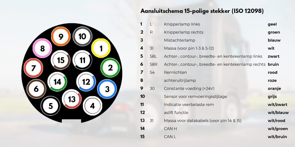
The ISO 12098 connector provides a standard 24V connection for lighting and auxiliary functions between the truck and trailer. The connector replaces the 7-PIN N and S connectors with connector single connector, ensuring a clear connection for lighting in vehicle construction. It is currently the most widely used wiring diagram for trucks.
With the rise of electric trucks and heavy-duty electric vehicles (e-trucks), the 15-PIN connector in accordance with ISO 12098 remains the standard for reliable communication between vehicle and trailer.
Nevertheless, there are a few points of interest in practice:
Different plug types occur in vehicle construction, each with its own standard and application. The table below shows at a glance which connector is used for what.
| Connector | Standard | Voltage | Typical application |
|---|---|---|---|
| 7-PIN connector | ISO 1185 | 24V | Basic lighting for trucks and trailer |
| 7-PIN S-connector | ISO 3731 | 24V | Additional functions such as rear fog light and reversing lights |
| 13-PIN connector | ISO 11446 | 12V | Passenger car with trailer or caravan |
| 15-PIN connector | ISO 12098 | 24V | Modern truck-trailer combinations (replaces N + S) |
The 15-PIN ISO 12098 connector has become the standard in modern vehicle construction, as it combines the functions of both N and S connectors in one connector. This simplifies cabling, reduces the number of connections and allows for additional signals such as CAN-bus and sensor information.
In many electric tractors, the ignition switched power supply does not automatically run via PIN 15 as it does in diesel vehicles. Check the vehicle documentation first: some manufacturers put PIN 15 on an auxiliary relay or require a software configuration. In practice, LED lighting that depends on a stable +24V on PIN 15 often requires a switching module or CAN-controlled relay control.
Pin 14 (CAN H) and pin 15 (CAN L) handle CAN-bus communication. Mass for the data cabling runs via PIN 13 (white/red). Please note: in some older ISO 12098 implementations, PIN 15 is used solely for contact-switched power supply without CAN functionality. Always check the scheme for the specific tractor and semi-trailer.
LED lighting draws significantly less current than incandescent bulbs, which means the vehicle may detect a bulb failure. With 24V CAN-bus systems, you can resolve this using CAN-bus solutions or resistor modules that simulate power consumption. When used in conjunction with ISO 12098, you should also check that the adapter transmits all relevant pin functions. See also our article on canbus interference.
The ISO 12098 combines the functions of ISO 1185 (N-plug, basic lighting) and ISO 3731 (S-plug, additional functions) in one connector. PIN 1 to 8 broadly cover the N-plug functions, PIN 9 to 13 the S-functions, and PIN 14 and 15 are added for CAN-bus communication. When converting, a 1-to-1 adapter is not possible: use a specifically designed adapter or replace the entire wiring.

A selection of LED lighting for trucks and trailers.
A comprehensive overview of our LED vehicle lighting and accessories.
Plug-&-play lighting kits, cabling and lighting for bodybuilders.
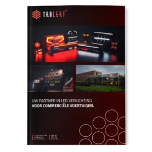
What TRALERT® can do for you as a partner in LED vehicle lighting.
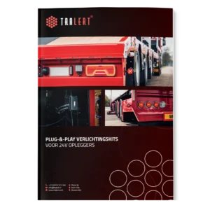
Plug-&-play kits, cabling and lighting for 24V semi-trailers.
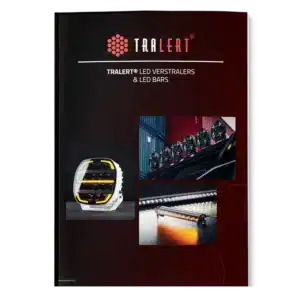
A selection of high-quality LED driving lights and LED bars.
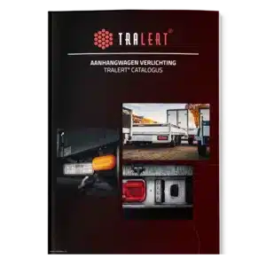
Lighting, wiring harnesses and accessories for trailers.
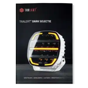
The TRALERT® DARK LED range.
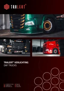
Work lights, rear lights, driving lights, beacor bars and more for DAF Trucks.
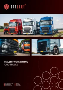
Work lights, rear lights, driving lights, beacor bars and more for Ford Trucks.
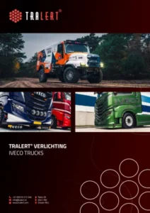
Work lights, rear lights, driving lights, beacon bars and more for Iveco.
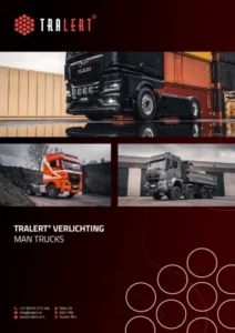
Work lights, rear lights, driving lights, beacon bars and more for MAN.
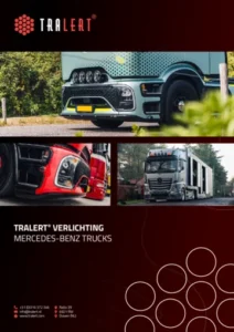
Work lights, rear lights, driving lights, beacon bars and more for Mercedes-Benz Trucks.
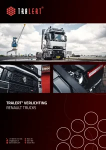
Work lights, rear lights, driving lights, beacor bars and more for Renault Trucks.
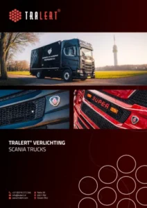
Work lights, rear lights, driving lights, beacor bars and more for Scania.
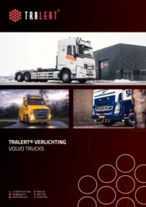
Work lights, rear lights, driving lights, beacon bars and more for Volvo Trucks.
The catalogue opens in a new tab. Can’t see it?
Open the catalogue (PDF)Two questions, in 30 seconds.
TRALERT® works with a dealer network. Dealers can view current stock levels, place orders online on account and receive a product feed for their online shop or system. We assess each enquiry internally and will let you know within 1 to 2 working days whether a partnership is possible.
You can purchase TRALERT® lighting through our partners, either locally or online. Simply provide your details, and we’ll find the partner best suited to help you.
Would you prefer to find a stockist yourself?We will assess your enquiry internally. You will hear from us within 1 to 2 working days to let you know whether a partnership is possible.
We’ll let you know within 1 to 2 working days which partner will be able to assist you further.