Specialised partner in LED vehicle lighting

Showing all 8 results
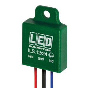
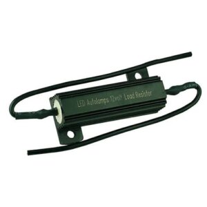
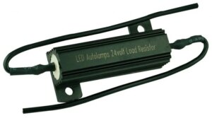
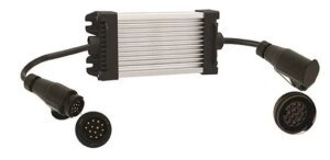
Modern vehicles constantly monitor the operation of electronic components via the CANBUS system. If you connect LED lighting, it may flash or fail: LED consumes less power than an incandescent bulb, causing the system to wrongly detect a fault. Below are the most commonly used solutions.
An error message after connecting LED lighting does not automatically mean that the CAN network is faulty. Often, the towing vehicle’s electronic lamp monitoring system does not recognise the low current draw of the LED lighting as that of a functioning light. You should therefore first check the plug connection, pin configuration, earth connection and cabling. If the lamp monitoring system is found to be the cause, the appropriate solution depends on the system voltage, the light functions involved and the connection between the vehicle and the bodywork or trailer.
| Situation | Possible solution | What to look out for? |
|---|---|---|
| A single monitored light function triggers an error message or the indicator flashes too quickly | A suitable load resistor | Choose a 12V or 24V version and take heat build-up into account during mounting. |
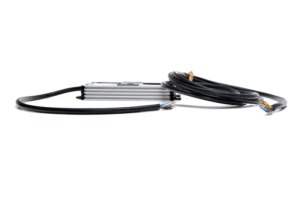
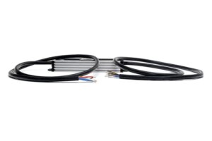
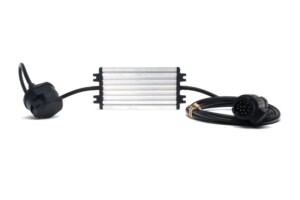
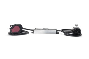
| Several light functions trigger fault codes on a trailer or semi-trailer | An LED control box | Check the system voltage, the number of supported functions and the connection type: open-wire, 13-PIN or 15-PIN. |
| The interference occurs in an individual LED light | A suitable module for each light, such as an i-LS microprocessor | Check that the module is compatible with the light, the light function and the vehicle. |
| You are putting together a new lighting system | LED lighting suitable for the relevant lamp monitoring system, where applicable combined with a control box | Ensure that lights, wiring harnesses and electronic monitoring systems are pre-configured to work together. ‘CAN-bus proof’ is no guarantee that every combination will work without modification. |
A resistance increases the electrical load on an individual circuit. This can be a solution when a single monitored light function triggers a fault message due to the low current draw of LED lighting. A resistance consumes energy itself and generates heat. The correct value and installation location are therefore important.
A control box is designed for a connection where multiple light functions need to be coordinated. The TRALERT® range includes, amongst other things, 12V versions with a 13-PIN connection and 24V versions with open wire or a 15-PIN connection. Which version is suitable depends on the towing vehicle, the plug connection and the functions that are electronically monitored.
Are the lights flashing, has a light failed, or does ‘light fault’ appear on the dashboard? First, follow our steps for diagnosing a CAN-bus fault in LED lighting. If you’d like to know what the indicator means, read our explanation of canbus proof LED lighting.
Are you developing a lighting package for series production or a complete vehicle body? TRALERT® helps to tailor the lighting, connections, wiring harness and any control box to your specific application.
When fitting additional lighting to a vehicle, a different approach is required compared to simply replacing an existing light. Work lights, warning lights or interior lighting require a suitable power supply and control system. Whether you use a separate circuit, relay or control box for this depends on the vehicle and the functions you wish to connect.
Before mounting, check which connections and loads the vehicle manufacturer permits. This will prevent additional lighting from affecting the existing lamp monitoring system or other vehicle functions. In series production, TRALERT® can help to specify lighting, wiring harnesses, connectors and control systems as a single integrated system.
TRALERT® operates through a dealer network. Prices, stock levels and online ordering are therefore only available to business customers with an account.
We assess every enquiry internally and will let you know within 1 to 2 working days whether a partnership is possible.
For your own use?Find a stockist
Would you prefer a quote first?Add this product to your quotation request and send it off when you’re ready.